Cart

Added to cart

Go to cart

Your order qualifies for free 2-day shipping and easy returns

IR Temperature Sensor with GigE (Manual Focus)

FLIR A35

Model: FLIR A35, f=9 mm with SC kit Go to Product Support
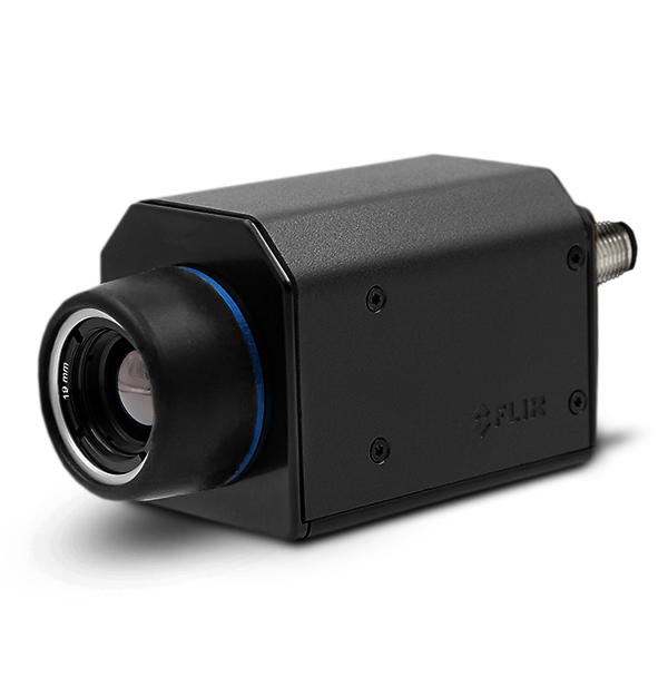
product image

The FLIR A35 is a thermal imaging temperature sensor for condition monitoring, process control/quality assurance, and fire prevention applications. The A35 integrates seamlessly into existing systems, offering comprehensive visual temperature monitoring. As part of the Ax5-Series, the A35 is among the only thermal imaging temperature sensors on the market to provide temperature linear output through GenICam™ compliant software.

Sales Contact Contact Sales
  • Affordable and Compact

    At just 4.1 × 1.9 × 1.8 in, the A35 brings thermal imaging to your smallest spaces at an affordable price.

  • Plug-and-Play

    Easy setup thanks to GigE Vision and GenICam compliance and GigE Vision lockable connector.

  • Connect Multiple Cameras

    Synchronize between multiple cameras for greater coverage and communication, or for stereoscopic applications.

Contact Sales

Want more information on this product?

Call +852 27928955 to speak with a knowledgeable specialist.

Specifications
Digital I/O connector type
12-pole M12 connector (shared with Digital Synchronization and External power)
Digital Inputs
General Purpose, 1× opto-isolated, "0" <1.2 VDC, "1" = 2–25 VDC.
Digital Output Purpose
General purpose output to ext. device (programmatically set)
Digital Outputs
1× opto-isolated, 2–40 VDC, max 185 mA
EMC
•EN 61000-6-2 (Immunity) •EN 61000-6-3 (Emission) •FCC 47 CFR Part 15 Class B (Emission)
f-number
1.1
Image Frequency
60 Hz
Thermal Sensitivity/NETD
<0.05°C @ 30°C (86°F) / 50 mK
Accuracy
±5°C (±9°F) or ±5% of reading
Communication & Data Storage
Digital I/O connector type
12-pole M12 connector (shared with Digital Synchronization and External power)
Digital I/O isolation voltage
500 VRMS
Digital I/O supply voltage
2–40 VDC, max 200 mA
Digital Inputs
General Purpose, 1× opto-isolated, "0" <1.2 VDC, "1" = 2–25 VDC.
Digital Output Purpose
General purpose output to ext. device (programmatically set)
Digital Outputs
1× opto-isolated, 2–40 VDC, max 185 mA
Digital Synchronization Connector Type
12-pole M12 connector (shared with Digital I/O and External power)
Ethernet
Control and image
Ethernet Communication
GigE Vision ver. 1.2 Client API GenICam compliant
Ethernet Connector Type
RJ-45
Ethernet Image Streaming
8-bit monochrome @ 60 Hz Signal linear/ DDE Automatic/ Manual Flip H&V 14-bit 320 × 256 pixels @ 60 Hz Signal linear/ DDE Temperature linear GigE Vision and GenICam compatible
Ethernet Power
Power over Ethernet, PoE IEEE 802.3af class 0 Power
Ethernet Protocols
TCP, UDP, ICMP, IGMP, DHCP, GigEVision
Ethernet Standard
IEEE 802.3
Ethernet Type
Gigabit Ethernet
Synchronization in
1×, non-isolated
Synchronization in - purpose
Frame sync in to control camera
Synchronization in - type
LVC Buffer @3.3V, "0" <0.8 V, "1" >2.0 V.
Synchronization out
1×, non-isolated
Synchronization out - purpose
Frame sync out to control another Ax5 camera
Synchronization Out - type
LVC Buffer @ 3.3V, "0"=24 MA max, "1"= –24 mA max.
Imaging & Optical
Detector Pitch
17 µm
Detector Time Constant
Typical 12 ms
Detector Type
Focal plane array (FPA), uncooled VOX microbolometer
Field of view (FOV)
13° × 10°
FLIR Screen-EST Mode
No
f-number
1.1
Focal Length
25 mm (0.98 in.)
Focus
Fixed
Image Frequency
60 Hz
IR Resolution
320 × 256 pixels
Spatial resolution (IFOV)
0.680 mrad
Spectral Range
7.5–13 µm
Thermal Sensitivity/NETD
<0.05°C @ 30°C (86°F) / 50 mK
Measurement & Analysis
Accuracy
±5°C (±9°F) or ±5% of reading
Atmospheric transmission correction
Automatic, based on inputs for distance, atmospheric temperature and relative humidity
Camera size (L x W x H)
107.8 × 49.6 × 46.6 mm (4.2 × 1.9 × 1.8 in.)
Emissivity Correction
Variable from 0.5 to 1.0
Measurement Corrections
Global object parameters
Object Temperature Range
-25°C to 100°C (-13 to 212°F) / –40°C to 550°C (-40 to 1022°F)
Optics Transmission Correction
Automatic, based on signals from internal sensors
Reflected apparent temperature correction
Automatic, based on input of reflected temperature
General
Base Mounting
4 × M3 thread mounting holes (bottom)
Housing material
Magnesium and aluminum
Package Includes
Hard transport case Infrared camera with lens Base support Cable tie (2 ea.) Ethernet cable CAT-6, 2m/6.6 ft (2 ea.) FLIR ResearchIR Standard 4 Focus adjustment tool Gooseneck Mains cable kit (UK,EU,US) PoE Injector (power over Ethernet) Printed documentation Table stand
Packaging Size
370 x 180 x 320 mm (14.6 x 7.1 x 12.6 in.)
Environmental & Certifications
EMC
•EN 61000-6-2 (Immunity) •EN 61000-6-3 (Emission) •FCC 47 CFR Part 15 Class B (Emission)
Encapsulation
IP 40 (IEC 60529) with base support mounted
Humidity (Operating and Storage)
IEC 60068-2-30/24 h 95% relative humidity 25°C to 40°C (77°F to 104°F)
Operating Temperature Range
–15°C to +50°C (+5°F to +122°F) The operating temperature range assumes that the camera is mounted on the base support (included in the package) or a similar type of heatsink.
Shock
25 g (IEC 60068-2-27)
Storage Temperature Range
–40°C to 70°C (–40°F to 158°F)
Tripod Mounting
UNC ¼"-20 (on three sides)
Vibration
2 g (IEC 60068-2-6 & MIL-STD810G)
Power
External Power Connector Type
12-pole M12 connector (shared with Digital I/O and Digital Synchronization )
External Power Operation
12/24 VDC, < 3.5 W nominal < 6.0 W absolute max
Voltage
Allowed range 10–30 VDC
Related Documents
Export Restrictions

Export Restrictions

The information contained in this page pertains to products that may be subject to the International Traffic in Arms Regulations (ITAR) (22 C.F.R. Sections 120-130) or the Export Administration Regulations (EAR) (15 C.F.R. Sections 730-774) depending upon specifications for the final product; jurisdiction and classification will be provided upon request.

FLIR A35 - Model: FLIR A35, f=9 mm with SC kit

Change Selection